
“For those unfamiliar with the quirks of design patent practice, it might be tempting to rely on your patent draftsperson to prepare what they think are adequate drawings, copy the mostly boiler-plate specification language, and just file the application. But that can be a costly mistake.”
As one of about 46,000 registered practitioners in the United States, most of us are unfortunately too well acquainted with Section 101, 102, and 103 rejections from the U.S. Patent and Trademark Office (USPTO). But it may be surprising that most rejected design patent applications are not rejected under these sections. Instead, the least favorite number of the design patent practitioner is 112. While Section 112 rejections on utility applications are generally easily overcome, that is often not always the case with such rejections on design applications.
Since there are only about 30,000 design applications issued each year, each of the 46,000 registered practitioners handle on average less than one design application per year! So, for those unfamiliar with the quirks of design patent practice, which is most of us, and since design patent applications have a relatively high allowance rate of 84% (see the USPTO Data Visualization Center/Design Data page, it might be tempting to rely on your patent draftsperson to prepare what they think are adequate drawings, copy the mostly boiler-plate specification language, and just file the application. But that can be a costly mistake.
Indeed, while the USPTO has shied away from using the term “fatally flawed” of late, the fact is that inadequate patent drawings may render a design patent application dead on arrival the moment you press the “Submit Application” button in EFS-Web. You may have a patent-pending zombie application creeping around for about a year before you realize it’s dead due to 112 rejection issues. And that’s uncomfortable news to have to relay to your client.
So how do we prevent these types of rejections? The top three rejections for design patent applications, all of which are due to insufficient disclosure in the original drawings, are for non-enablement, inconsistency, and ambiguousness. Let’s take each of these in-turn and address how to prevent such rejections in the first place.
Section 112 Rejections for Non-Enablement
Non-enablement occurs when a person skilled in the art (POSITA) would be unable to make the design due to inadequacy of the disclosure, either because of the drawings, specification, or both. Remember, as an article of manufacture, the design must be fully disclosed so that a POSITA can make the design, even those parts of the design that one might consider obvious or unnecessary to illustrate. For instance, this can easily happen on the rear or bottom surfaces of a design. Take the calculator of D605,220, for example. These are the original drawings:
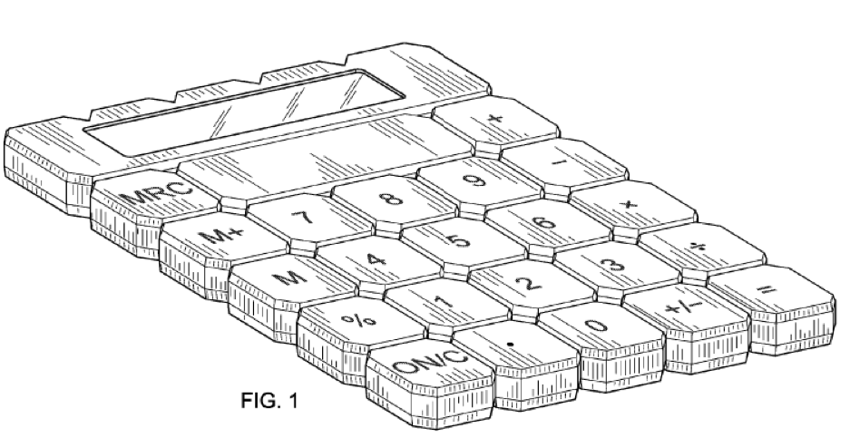
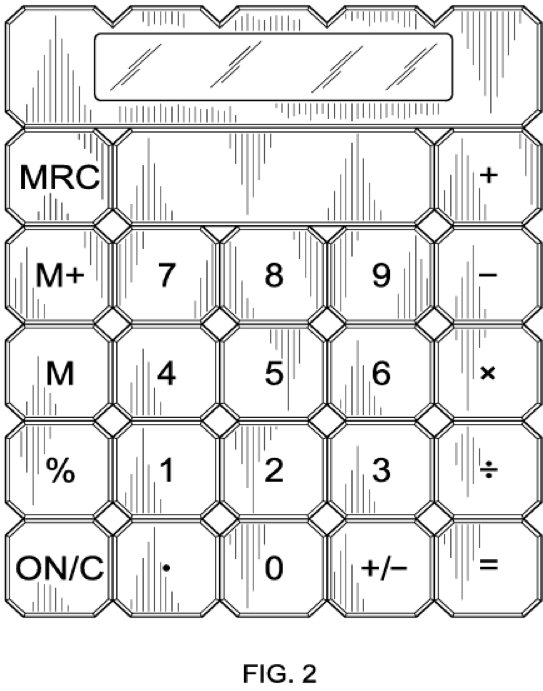
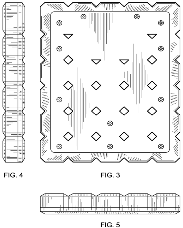
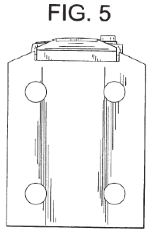
At first glance, these appear impressive, particularly if you’re used to utility patent drawings which do not need all of the shading detail. But these drawings were rejected for several reasons, one being that certain portions of the rear side shown in FIG. 3 are non-enabled. So, in FIG. 3 you think those are 12 screws, do you? Just how deeply inset are the heads of these alleged screws? Or are they sitting above a plate that itself is recessed? Or are they just round flat stickers that have a screw-head design printed on them? We just can’t tell from FIG. 3 alone. About the only thing we know (from FIGS. 4 and 5) is that the screw heads don’t project downwardly beyond the plane of the bottom surface of the calculator. But that’s not enough information to actually make one of these without “resorting to conjecture,” a phrase you’ll become familiar with if you file many design patent drawings like the ones above.
Now it’s tempting to quickly glance at the drawings you receive from your draftsperson and be casually impressed. After all, the extensive shading required on design patent drawings gives them a certain impressive beauty. But it’s important to look at the details such as these screws and ask if there are multiple ways of interpreting the drawing disclosure. In this case, there are but a bottom perspective view would have made all of the difference. A perspective view, taken from the correct angle, can show the depth of features that otherwise would be impossible to know. So, while the official patent office line is that seven drawings are typically required for a design patent application (all six sides and a perspective view), it’s really often the case that eight drawings should be submitted by including two perspective views from opposing sides. One perspective view should show the top, front and side of the object, while the other perspective view should show the bottom, back, and opposite side. That certainly would have helped in this case, and not just for the problem of non-enablement, as we’ll see. But at this point it’s too late to add a bottom perspective view since such a view would almost certainly add “new matter” that wasn’t disclosed in the original set of drawings. So that’s not an option for overcoming this rejection once the original drawings are filed (but remember that it is a great solution in yet to be filed cases).
Another drawing view that would have been valuable in this case is a cross-sectional view across one or more of the screws. This would show how deep these screws are, and that they are in fact screws. Cross-sectional views are vital for designs having deep or complex wells or recesses. Something like an undulating tube or a telescoping camping water cup can be completely described by a single cross-sectional view.
However, it is also easy to show too much information in a cross-sectional view. For example, the inside of a housing may not be important to the overall outer appearance of a design, but if you disclose it then it’s considered part of the claimed design and therefore must be enabled. In such cases you may wish to put any internal details inside an unclaimed inner broken line, indicating that the internal contents of the box are not part of the claimed design.
Also, a cross-sectional view is most helpful when you’re dealing with a radially-symmetric object, where it’s clear that a cross-section across a diameter of the design is the same as that across any other diameter. But in this calculator case, even if we had a cross-section across, say, two of the screw holes on one side, there’s nothing that shows if the apparent screw holes on the other side are the same. We can indicate in the specification that FIG. 10 is a cross-sectional view across screw holes of the design, all screw holes having the same structure” or some such. But it can be easy to miss elements that, without some type of overt description or drawing, are ambiguous.
So what do we do now that we’ve received this rejection?
In this case, we were lucky that a simple technique saved the day: reducing unenabled elements to broken lines to disclaim them. In design patent practice we can change solid lines to broken lines to disclaim problematic elements as long as the resulting claim is not so radically different as to introduce new matter. This removes the problematic elements from the claimed design, and therefore enablement of such elements is not required. In this case, reducing the 12 screws to broken lines overcame this part of the rejection. We’re basically saying with broken lines that “something like screws can go here, or not… it really doesn’t matter.” So interestingly, the solution to this dilemma in this case actually broadens the scope of protection, since now rivets or thumb screws or just about any type of element at these locations, something that varies from the appearance of screws wildly even, would not give an advantage to an infringer of this patent.
So, we’ve overcome the problem of enablement with regard to lack of sufficient disclosure in this case. But there are more problems with these drawings than non-enablement.
![[[Advertisement]]](https://ipwatchdog.com/wp-content/uploads/2024/04/Patent-Litigation-2024-banner-938x313-1.jpeg)
Section 112 Rejections for Inconsistency
Inconsistency between figures refers to the problem where both figures, as shown, cannot coexist. Either one is correct or the other, but not both. For example, with the calculator above, FIG. 4 shows a side view that has (on the right side) notches all across the bottom side of the calculator. These notches or ridges should, therefore, be evident on the bottom view as horizontal lines traversing the entire bottom surface; but, as you can see, there are no such horizontal lines shown on the bottom surface in FIG. 3. FIG. 4 may be correct, or FIG. 3 may be correct, but they cannot both be correct. As such, a POSITA cannot possibly make such an object, and therefore the disclosure is insufficiently disclosed.
The wording from the USPTO Examiner in this case reads as follows:
The claim is indefinite and nonenabling because the exact appearance of the bottom of the design cannot be understood from the disclosure. Elements of the bottom surface are shown in Figures 3, 4 and 5, however these figures do not appear to agree with each other as to how the surface appears:
Figure 3 shows the bottom surface to have beveled edges, formed from a single piece of material, notched at the top where it meets the notched sides, and having a flat, rectangular bottom surface.
Figure 4 shows each of the notched areas on the right and left sides of the design to bevel inwards individually to the bottom surface and for the bottom surface to have faceted furrows extending across the bottom surface from the left to right side.
Figure 5 shows single beveled pieces across the front and rear sides, leading to the bottom surface, but the beveled pieces are flat where they meet the notched sides, not notched as shown in Figure 3.
None of these FIGS. 3-5 agree with each other completely, which could have been fatal to the application but for the saving grace of the broken line, again, which we’ll address below. Had I at the time required an alignment sheet from my draftsperson, it’s very likely that he would have caught the problems with FIG. 4 even before delivering the first draft of the drawings to me for review! An alignment sheet places each view next to the other relevant views and includes reference lines between each feature across views. For these drawings the alignment sheet would have looked something like this:
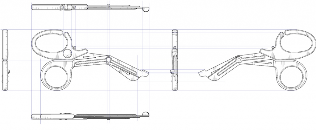
Typical alignment sheet showing correspondence between elements across views
Requiring an alignment sheet from your design patent draftsperson is a must, and often results in the correction of consistency errors that you will never see, since the problem will be evident and fixed before the drawings are delivered to you. But you need to specify to your draftsperson that the alignment sheet should include internal elements, not just the outside edges of the design.
Once drawings like the above are filed, there is a very real possibility that they contradict each other to such an extent that it’s impossible to fix them. In the calculator case, we were fortunate that the edge lines between the outermost bezels and the bottom surface were defined in both the side and front/rear elevational views, even though they were not shown in FIG. 3, the bottom view. When that happens, you are free to draw the line where it’s missing in one view since there’s support for it in at least one other view. In this case, we could add the following edge lines on the bottom surface of FIG. 3:
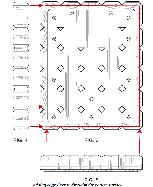
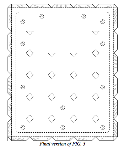
We are then able to disclaim the entire bottom surface by reducing the bottom edge lines to broken lines, removing all of the shading on the bottom surface, and reducing all of the features of the bottom surface to broken lines. It’s arguable that we didn’t need to put the triangular and diamond-shaped apertures of the bottom surface in broken lines, but it doesn’t hurt to do so, again because that just makes the design more general and increases the scope of the claim. Now we can add the broken line disclaimed bottom surface to FIGS. 4 and 5, make the bezels consistent with FIGS. 1 and 2. Now you can file your amended drawings showing an enabling disclosure in your response to the USPTO’s 112 Office Action.
An overriding requirement for answering any office action, of course, is whether or not the replacement drawings you’re submitting to the USPTO will protect what your client wants to be protected. While it’s beyond the scope of this article to discuss the initial interview with the client and how to ascertain what’s important to protect for your client, clearly you shouldn’t just fix the drawings for expediency rather than accuracy. It’s helpful when getting an office action on a design case to contact the client for the “current version” of the design and steer any replacement sheets towards that if possible. Obviously, the current version must be within the scope of the initial disclosure, but sometimes (as in this calculator case, for example), for manufacturing reasons or otherwise, the client may have opted for a completely flat bottom for the calculator, no screw holes (since they’re now ultrasonically welding the enclosure shut), ridges along the bottom after all, etc. The first Office Action on a design patent application will likely be a year or so after filing, and in the manufacturing world a lot can happen in a year and the client may not think to let you know about something that materially changes the appearance of their product. So, it doesn’t hurt to ask.
Section 112 Rejections for Ambiguity
The final common type of Section 112 rejection is for ambiguity, such as when an element is disclosed in such a way that its shape is undeterminable.
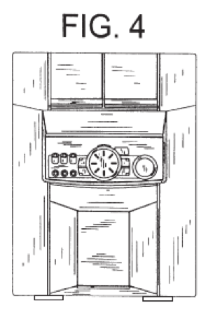
Audio Equipment with Feet, front elevational view (D416,557 modified)
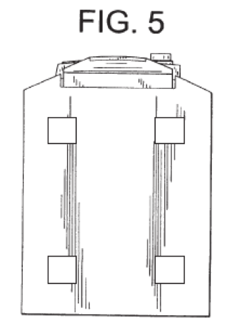
Which of these drawings is correct for the bottom plan view, FIG. 5, given FIG. 4 above?
A common case where this rejection is necessary is with an item that has surface-contacting feet, such as an audio component. Often if the bottom plan view, which is normally not that important to the overall design, is omitted, then the combination of the front, rear, left, and right elevational views will not be enough information if the feet are not shaded to indicate if they are, for example, round or square. Such feet tend to be thin and easy for the draftsperson to skip in terms of shading as unimportant. But every surface in a design patent should be shaded to indicate its contoured shape, even thin little unimportant feet on the bottom of a stereo receiver.
Also, even if a bottom plan view seems unimportant, it can help you overcome an ambiguousness rejection if it provides the missing information. In this case, if the original drawing showed non-shaded feet, it would be a simple matter to add the appropriate shading (based on the shape of the feet in the bottom plan view) and file a replacement sheet without adding new matter. But without the bottom plan view, there’s no telling if the feet are round or square, and so you’ll have to disclaim them by converting them to broken lines. Now that may be okay, as it technically broadens the disclosure, but what if the feet were considered an important design attribute by the client? These are some of the things to consider when deciding what views to have your draftsperson draw.
In Part II of this article we will consider the fourth most common design patent trap: objections to the drawing disclosure.
![[Advertisement]](https://ipwatchdog.com/wp-content/uploads/2024/05/Quartz-IP-May-9-2024-sidebar-700x500-1.jpg)
![[Advertisement]](https://ipwatchdog.com/wp-content/uploads/2024/04/Patent-Litigation-Masters-2024-sidebar-700x500-1.jpg)

![[Advertisement]](https://ipwatchdog.com/wp-content/uploads/2021/12/WEBINAR-336-x-280-px.png)
![[Advertisement]](https://ipwatchdog.com/wp-content/uploads/2021/12/2021-Patent-Practice-on-Demand-recorded-Feb-2021-336-x-280.jpg)
![[Advertisement]](https://ipwatchdog.com/wp-content/uploads/2021/12/Ad-4-The-Invent-Patent-System™.png)


Join the Discussion
6 comments so far.
Eileen McDermott
February 21, 2020 08:58 amHi ntocups – Yes, it’s here: https://ipwatchdog.com/2019/11/21/most-common-design-patent-application-rejections-how-to-avoid-them-part-ii/id=116264/ I’ve added the link at the end of Part I now. Thanks!
ntocups
February 20, 2020 10:43 pmThank you. Very helpful article. Has the rest of the series been published?
Curious Onlooker
December 10, 2019 07:37 amWritten by a lawyer for other lawyers, not the laymen looking for a first-step.
These articles appear to be designed to confound and confuse the layperson into purchasing the $99 book (why not $100?)
If I could quote the author, from another article:
“telling us what they do not have to be is not nearly as useful or informative as telling us what they do need to be.”
What a meaningless waste of words and space, for the layperson, looking for simple direction.
I can only assume the $99 book recommends the reader to the author?
I also wonder if the $99 book is self-published, on demand, by some printing company?
For those who want to know (and those who don’t):
The author of these comments has spent 40 years working in 4 countries, in 3 continents.
Let’s add to that, recreational travel from the Middle East to South America, from the entire East coast to Asia.
Having faced a clinical dilemma, and finding a solution, the last thing I need is countless pages of lawyer-esk, I’ve had enough of lawyers and courtrooms to last a lifetime.
Kevin Prince
November 22, 2019 02:52 pm@Just Wondering: “why can’t one argue that the claim encompasses both types of feet?”
Because ambiguous structure doesn’t meet the requirements of Sec. 112 for design patents. You have to provide enough information to show someone skilled in the art how to build one, and so “nothing can be left to conjecture” with design patent drawings. This is somewhat different than with utility patent applications, of course, where you can have optional solutions for things that don’t revolve around the point-of-novelty.
Charles Mauro
November 21, 2019 07:26 amKevin: Excellent article. I have been an expert witness in over 75 design patent cases and have seen all of the above repeatedly. Another major mistake corporations make when filing design patents is to reuse the CAD drawings from their utility patent application in their design patent. They do this to reduce the cost of an application. However, later should the design patent be asserted against an infringing party having the same visual design depicted in the utility patent gives the infringing party the ability to claim the product in the design patent is purely functional (non-ornamental). This can be overcome but it complicates the analysis during litigation and gives the defendant more options for attacking the design patent.
Charles Lee Mauro CHFP
President / Founder
Mauro Usability Science
Just wondering
November 20, 2019 09:58 amKevin:
Question regarding design patent claims. Looking at D’557, why can’t one argue that the claim encompasses both types of feet? In other words, the claim is broad, not ambiguous. Why don’t these types of arguments work?